SYSTEM DESIGN GUIDELINES

INTRODUCTION

Many variables must be considered when designing a cooling system. The chiller location, positioning and distance from the application are important considerations. The application type and number of chillers needed to serve a process also have bearing on the system design. The following section provides an overview of good practice when installing the chiller and cooling system.

Key points to consider in the successful installation of a protection water cooling system are as follows:
  • Chiller location and positioning
  • Frost protection
  • Chiller water circuit
  • Fill kit option
  • Electrical connection
  • Remote control panel
  • Chiller start-up

CHILLER LOCATION & POSITIONING

The Hyperchill and Hyperchill Plus range of products offer a robust and reliable cooling solution. The location and positioning of the chiller is critical to achieving and maintaining the correct cooling performance.

In general, most of the chiller range can be located both internally or externally. The following guidelines apply:

Internal Installation

Chiller models ICEP002, ICEP003 & ICEP005 have an Ingress Protection (IP) rating of 33 and must be located and installed internally.

Internal and External Installation

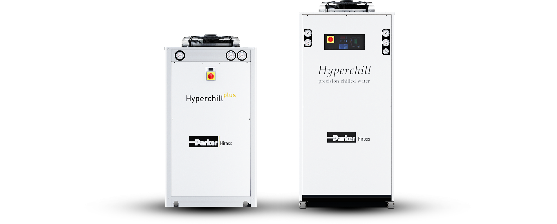
Hyperchill Plus models from ICEP007 and above are IP54 rated and are suitable for installation both internally and externally. This is also the case for the Hyperchill product range.

Chiller Positioning

Ventilation around the chiller is essential for maintaining system performance. The fundamental purpose of the chiller is to remove heat load from the water circuit to the local atmosphere. If the local environment is inadequately ventilated, heat will build up in the circuit and the chiller will sound and alarm. Please consider the following:

  • Position the chiller in a well-ventilated area.
  • Ensure the chiller has adequate free air space at the sides, rear and above the unit (please refer to the operation and maintenance manual for specific clearance details).

FROST PROTECTION

Exposing a water-cooled system to low temperature can result in frost damage to the chiller and water circuit. Frost protection should be considered in the following circumstances:
  • Chiller is installed externally (exposed to low ambient temperature).
  • Water temperature set-point is configured at <7oC
Two options can be employed to prevent frost damage. These options are as follows:
  • Include the ‘antifreeze heating’ option in the chiller specification.
    • Applicable for the ICEP007 and above.
  • Addition of antifreeze (ethylene glycol) solution to the cooling water.
    • Minimum acceptable glycol content is 20% V/V.
    • The total volume of glycol should not exceed 40% V/V.

In instances where a chilled water temperature of <7oC is required an antifreeze solution must be added to the cooling process water.

The following table provides guidance on the glycol % required to meet specific outlet water temperatures:
Outlet water temperature (oC) Ethylene glycol (%vol.) Ambient temperature (oC)
4 5 -2
2 10 -5
0 15 -7
-2 20 -10
-4 25 -12
-6 30 -15
Salient points to consider when using ethylene glycol in the chilled water system are as follows:
  • Do not use automotive antifreeze products. These products often have additives that can reduce heat transfer efficiency and potentially damage the chiller.
  • Only use inhibited glycol products. Uninhibited products can be corrosive to the water cooling system.
  • Do not mix different glycol solutions and brands. Different products can contain a range of incompatible inhibitors that can separate out and cause filtration and pump issues.
  • Check local regulations and environmental policy. Disposal, ground water contamination and drainage may have to be considered.
  • Regular ‘tap’ water can be used in most installations. However, the use of de-ionised, de-mineralised or distilled water may be preferable when using glycol to eliminate the risk of any impurities effecting the efficiency of the glycol inhibitors.
  • System hygiene and maintenance is important. The chilled water system should be flushed, cleaned and sanitised before adding a new glycol / water mix.

CHILLED WATER CIRCUIT

The following points should be considered when designing the complete chilled water circuit:
  • Isolating valves should be fitted at the inlet and outlet of the chiller.
  • Regulating valve should be fitted in the flow pipework (refer to installation diagrams).
  • Manual bypass with flow regulating valve should be installed to maintain appropriate flow through the process and chiller.
  • Filter should be considered / installed in the flow pipework entering the process.
  • The fill kit type (manual ambient or pressurized) should be correct for application.
  • Pipework minimum diameter is critical to achieve the design flowrate.
  • Pipework material is critical in cases where a non-ferrous system is required.
  • Trace heating of external pipework may be required if glycol is not installed.
  • Auto air vents should be installed at high point in water circuit.
  • Care should be taken when connecting pipework to the threaded connections on the chiller. Ensure adequate retention of the chiller connections when tightening, to prevent damaging the chiller.
  • Pipework should be flushed then leak tested with water prior to re-filling with an appropriate antifreeze mix.


WATER FILL KIT OPTIONS

The appropriate water fill kit should be selected based on the chiller installation requirements. The options available are as follows:

PRESSURISED WATER FILL KIT

This option allows for the installation of the chiller in a closed water circuit. The kit contains an expansion vessel, pressure relief valve, pressure reducing valve, pressure gauge and drain cock.

The chiller can be configured with the water fill kit already installed. Alternatively, the kit can be supplied separately to the chiller.

NOTE: After commissioning, the mains water supply can be isolated locally.

AMBIENT WATER FILL KIT

The ambient water fill kit can be used in open water circuit systems.

WATER FILL KIT OPTIONS

  • Open circuit version design, models ICEP002 to ICEP005, includes water filling on the top cover and an external visual indicator.
  • Models from ICEP007 and above can be supplied with an externally fitted water fill kit. Alternatively, the kit can be supplied loose.

The picture below shows the ambient fill kit.

ELECTRICAL CONNECTION

Electrical work should be undertaken by a qualified technician. Please review the manual prior to completing the electrical commissioning of the chiller.

Points to consider:
  • A local isolator should be installed close to the chiller.
  • The power supply should be protected using an appropriately sized D rated fuse / breaker.
  • After installation, the unit should be checked for the correct phase rotation.

REMOTE CONTROL PANEL

The Hyperchill range has the option to include remote control. The chiller can be controlled remotely through a two control levels.

Base Level Control
  • Chiller On / Off control
  • Chiller On / Off Signal
  • General Alarm Signal
Advanced Control
  • Allows all control options on the advanced microprocessor board

CHILLER START UP

Please consult the operation and maintenance guide and follow the appropriate steps. Fundamental checks include the following:
  • Ensure the pipework is fully leak tested and flushed prior to filling with water (or glycol mixture).
  • Check the phase protection device in the electrical panel. Green and orange indicators should be visible on the device.