INTRODUCTION TO BIOGAS

Biogas is a renewable energy derived from organic materials such as plant matter and animal waste that is generally referred to as biomass. Biogas has become a key contributor to the existing and future energy supply. Biogas continues to replace and reduce the reliance on fossil fuels such as coal, oil and natural gas. Growth in the biogas market is expected to continue as demonstrated below:

WHAT IS BIOGAS?

Anaerobic digestion is the process that occurs when bacteria decompose organics materials in the absence of Oxygen. The gas that is generated when plant and animal waste is digested is referred to as Biogas. Biogas is primarily composed of Methane and Carbon Dioxide. Smaller amounts of Hydrogen Sulphide and Ammonia along with trace amounts of Hydrogen, Nitrogen & Carbon Monoxide are also present in the gas. The crude untreated Biogas also contain dirt and solid particulates and is often saturated with water vapour.

WHY DOES BIOGAS REQUIRE SPECIALIST TREATMENT?

Most of today’s digestion processes produce biogas that is saturated with water vapor and contains varying degrees of other impurities. These impurities may cause corrosion, deposits and damage to equipment, and they should be removed before biogas is used to produce energy.

Gaseous constituents that should be removed (or reduced) along with water vapor include hydrogen sulphide, halogen compounds (chlorides, fluorides), ammonia, siloxanes and volatile organic compounds (VOCs). Biogas also contains dust and dirt particles, which should also be removed as part of the raw biogas treatment process.

The most common method of using biogas for energy production is through combustion in a gas engine or turbine to generate a combination of heat and electrical power (CHP). To allow the Biogas to be used as an efficient fuel source, most impurities must be removed from the crude gas.

Excess water vapour and other contaminants can result in numerous issues. The selection of effective biogas treatment is important for the following reasons:
  • Optimizing the cogeneration of electrical and thermal energy.
  • Reducing energy consumption on the plant.
  • Reduce equipment corrosion and plant maintenance costs e.g. reduced rusting of pipework & heat exchangers.
  • Reduce siloxane deposition in the CHP engine.
  • Reduce associated maintenance and running costs and increase engine efficiency.

Parker Biogas & Siloxane Removal Solutions

The diagram below depicts the typical treatment options for biogas generated from several processes:

Biogas Prefiltration & Dehumidification

It is generally accepted that a reduction in water content is beneficial to the CHP system, however, traditional methods, such as condensate traps and underground pipework, cannot achieve low dew points, consequently reducing the benefit of removing water. For underground pipework alone to have any real cooling effect, long runs of pipe are necessary, which is often impractical, expensive, and difficult to maintain and service.

It is also common to use “air conditioning” type chillers for biogas cooling, but these units are not designed to produce low-temperature water. They either result in higher gas dew points or end up operating well outside of their design limits, resulting in higher energy consumption and reduced service life.

It is therefore essential to use a cooling system, such as those in the Parker’s BioEnergy range, specifically designed to produce low dew points and operate in aggressive ambient conditions, such as those experienced in biogas applications.

An image of a typical BioEnergy SKID mounted package is shown below:

The SKID packages consist of the following technology:

PRE AND POST FILTERS

Biogas produced in anaerobic digesters and landfills contain foams, small solid particles in suspension, greases, particulates and other contaminants that must be removed from the gas by filtration prior to any downstream equipment or pipework. Failure to remove these impurities may lead to a malfunction of devices and processes downstream.

Parker low-pressure raw biogas filters are designed to combine particle retention efficiency with extremely low pressure-drop to produce clean, ready-to-use biogas, while minimizing service costs. The pre-filters increase process safety by protecting the tube bundle coolers from dirt and particle contamination. Used as a post filter, they remove particles form the gas stream protecting the downstream engine.

Tube Bundle Heat Exchanger

Parker’s high efficiency biogas resistant tube bundle heat exchangers, cool the warm gases that are saturated with moisture to force condensation. The Parker product can be used in landfill, sewage and biogas installations.

Water Separator (Cyclonic Type)

High separation efficiency with low pressure differential. Parker’s BioEnergy water separators remove condensed water from Biogas to deliver dry gas to the downstream equipment such as blowers, pipework and CHP engine.

BioEnergy Chiller

Parker’s Hyperchill BioEnergy chillers offer high efficiency performance in aggressive landfill and sewage environments. Special protective treatment on the condenser and copper piping ensure reliable operation.

The 4 Major Benefits of Dehumidifying Biogas

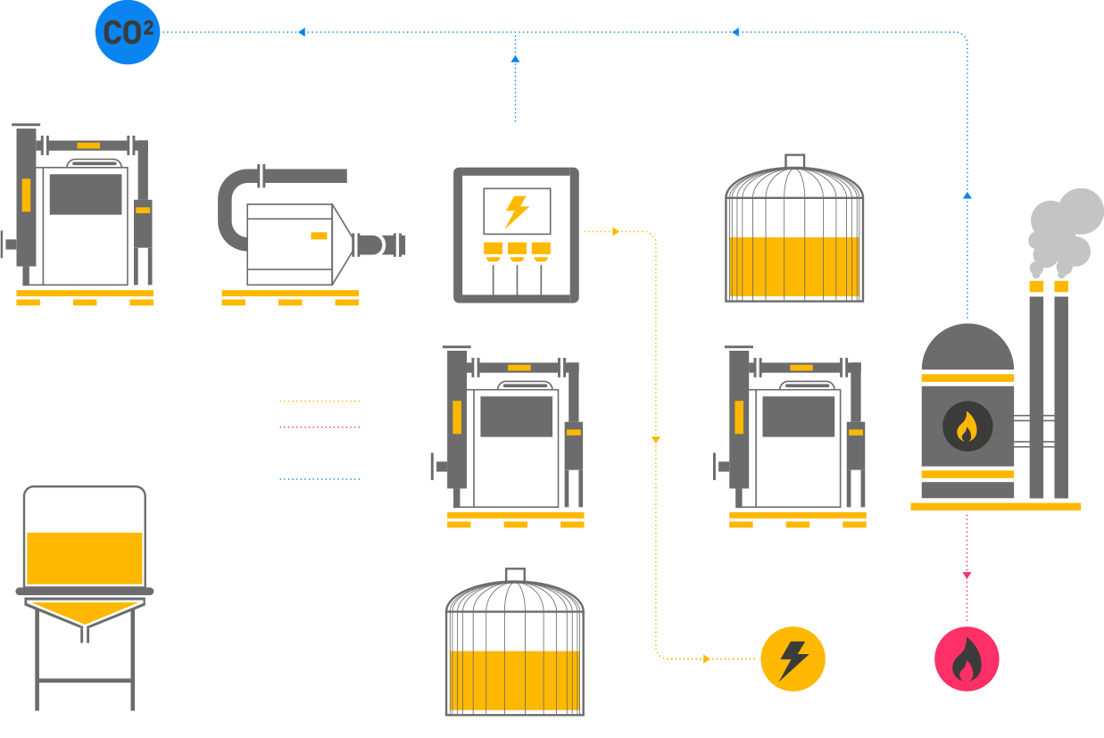
There are four major benefits of dehumidifying biogas. It will increase the energy content of gas, prevent the corrosion of pipework and system components, partially removes or reduces concentrations of specific gases, and complies with instructions from major gas engine suppliers.

1. Increases Energy Content of Gas

Raw biogas usually has a very high-water vapor content (between 30 and 100 g water per m3 gas), which equates to between 4 and 8 percent of the total gas composition and reduces the calorific value of the gas. Drying biogas to a dew point of 5oC reduces the moisture content to 1 percent, thus increasing the methane content by around 5 percent. This, in turn, increases the calorific value of the gas.

2. Prevents Corrosion of Pipework and System Components

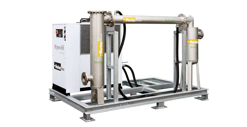
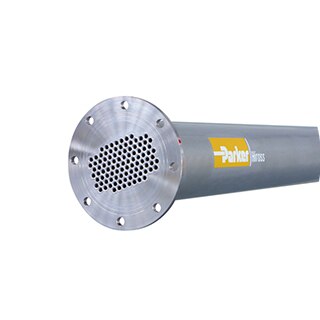
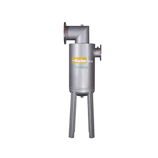
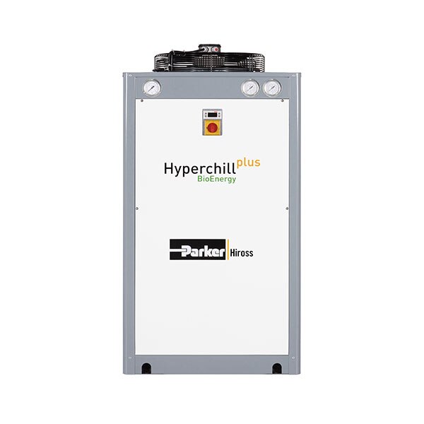
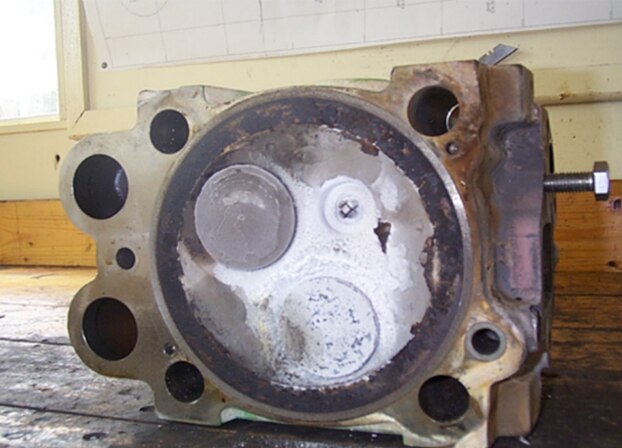
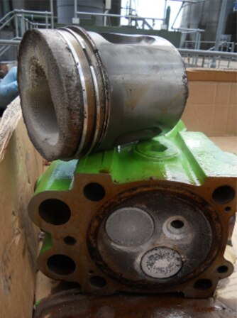
When ambient temperature drops, the gas cools, causing water vapor to condense in the pipeline. Condensate can combine with CO2, hydrogen sulfide (H2S), etc. to form an acidic compound that causes the accelerated corrosion of machines, gas scrubbers, pipelines, buffer vessels, sensors and instruments. The combination of H2S and water produces sulphuric acid and/or ionic hydrogen, and the combination of CO2 and water produces carbonic acid. The resulting acidic condensate is highly corrosive and will cause a rapid drop in the alkalinity of the engine oil. Drying the gas to a low dew point ensures that water vapor does not condense, thereby preventing the production of these corrosive acids.

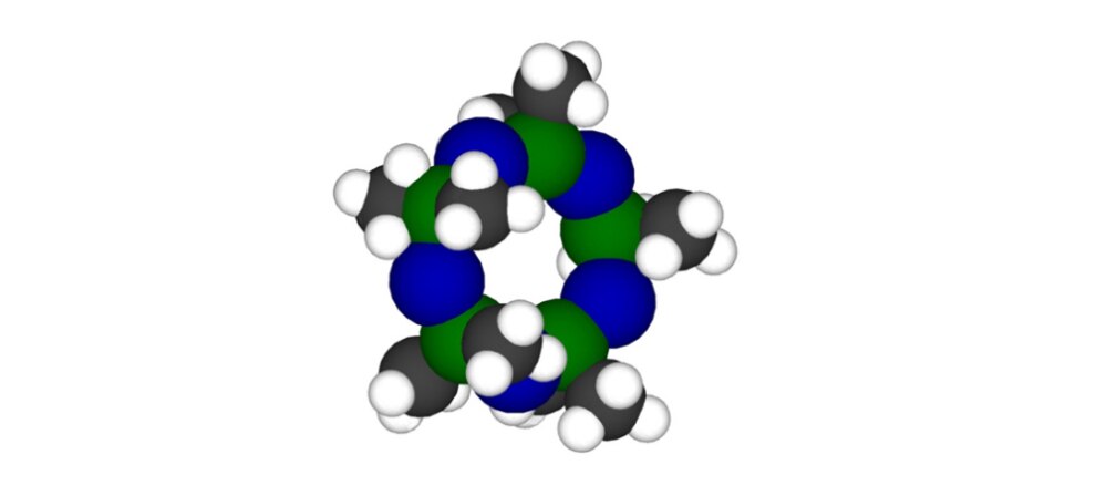
3. Partially Removes H2S, Ammonia, Siloxanes and Other Water-Soluble Gases

With efficient dehumidification, it is possible not only to remove the water vapor, but also to reduce the concentration of components, such as H2S, siloxanes, ammonia and halogen compounds, each of which dissolves in the condensed water. The partial or complete removal of these contaminants improves the efficiency of the whole plant and greatly reduces maintenance costs and plant downtime.

4. Complies with Technical Instruction of Major Gas Engine Suppliers

Unlike petrol and diesel fuels, gaseous fuels generally do not have to comply with strict quality specifications. For this reason, the manufacturers of cogeneration engines issue technical instructions to ensure the fuel gas is of sufficient quality to prevent any negative effects on engine performance and service life.

In terms of water content, all major engine manufacturers are clear in stating that water condensate in the fuel gas pipes or engine is NOT acceptable.

Installing a cooling system to dry the gas to a low dew point will ensure that water vapor does not condense in the gas pipe, which helps meet the technical instructions of the major gas engine suppliers.

Siloxane Removal Systems (SRS)

Recent years have seen a marked increase in the use of siloxane-containing products, a substantial amount passing through to waste products both in sewage and landfill sites. Siloxanes are organo-silicone compounds added to many personal care products such as shampoo, deodorants, soaps and creams. Siloxanes are chemically stable and pass through the waste water systems and are invariably present in almost all biogas.

As the gas produced from these sites is used to power biogas-to-energy units, a substantial increase in the effects of the siloxane contamination will be seen in the form of crystalline silicon dioxide (quartz/sand) building up on the combustion surfaces inside generating engines – if the process is left untreated. In addition to damaged engine components, affected engines run inefficiently and produce excessive emissions, particularly carbon monoxide and mono-nitrogen oxides (NOx). The image below shows Siloxane build up on a CHP piston crown and valves

The result is increased operating costs, decreased electricity production and increased pollutants.

There are various technologies commercially available for the removal of siloxanes from biogas. The most common are adsorption-based systems that use media that can be regenerative or non-regenerative.

For lower concentrations of siloxanes, activated carbon is often used as an adsorption media. Activated carbon can remove siloxanes to very low levels, but this method has high operation costs due to the need for the frequent replacement and disposal of hazardous spent media.

For medium to high concentrations of siloxanes, the higher capital investment of a regenerative system is often justified. Regenerative systems can reduce siloxanes to low levels with adsorption media lasting much longer than carbon-based systems. Parker’s Siloxane Removal System (SRS) can guarantee media life of 5 years, during which time siloxane concentrations will remain below 10 mg/m3.

 
The key features of the Parker SRS systems are:
  • Removes up to 98% of Siloxanes before they reach the engine.
  • Payback can be achieved in as little as 12 months.
  • Negligible pressure drop (<15 mbar).
  • ECU controlled for safe, automatic operation (via optional remote comms).
  • Media is non-toxic.
  • Gas sampling ports before and after media bed.
  • Robust stainless-steel construction (SS304 as standard or SS316 as an option).
  • Media can be designed to last up to 5 years – with minimal disposal costs.
  • Compact, skid-mounted design for ease of installation and reduced complexity of pipework.
  • Can be installed on pressure or suction side of blower.
  • Low power consumption & minimal maintenance keeps operating costs down.